|
 |
|
|
|
|
|
|
|
This method is useful for the elimination of cross-talk of optical lever deflection method, which is used in atomic force microscope (scanning force microscope)
|
|
|
|
|
|
|
|
|
|
United States Patent: "Angle Compensation Method"
Inventors: Satoru Fujisawa and Hisato Ogiso
Patent No.:US 6,407,806 B2
|
|
|
|
|
|
|
|
|
|
|
|
Abstract:
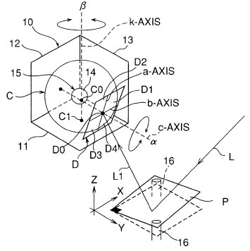
An angle compensation method compensates for the angle of the light-receiving surface of a photodiode disposed in an inclination detection device. The light-receiving surface is divided into four parts by an a-axis and a b-axis disposed perpendicular to each other and receives light reflected from an object surface that is an X-Y plane. The inclination detection device seeks the inclination of the object surface from changes in the irradiation position of the light reflected onto the photodiode light-receiving surface. The method includes the steps of fixing the light-receiving surface to a rotary stage that can rotate about a c-axis that passes through an intersection of the a-axis and b-axis and is perpendicular to the a- and b-axes and can rotate about a k-axis that is parallel to a Z axis of the object surface, and rotating the light-receiving surface about the c-axis and k-axis so that, when the light-receiving surface is projected onto the object surface, the a-axis aligns with a Y-axis and the b-axis aligns with an X-axis.
|
|
|
|
|
|
|
|
|
|
|
|
|
| ---> Related Patent in Japan |
|
|