Analysis of a transfer system
---
This page is still under construction. ---
1. Process Definition
We show some results of the analysis of a transfer systems TransferSys
defined by Fig.1.
TransferSys = (UI [|{|input, quit0, succ, ok, ng|}|] Transfer)
\ {|input, quit0, succ, ok, ng|}
Transfer = (Sender [|{|start,net,term,quit1,ack|}|] Receiver)
\ {|start,net,term,quit1,ack|}
UI = upload?ds -> input!ds -> (ok?a -> Wait [] ng?a -> UI)
Wait = cancel?b -> quit0!0 -> UI [] succ?u -> complete!0 -> UI
Sender = input?ds0 -> Check(ds0)
Check(ds0) = ((#ds0>0) & ok!0 -> start!0 -> Sending(ds0))
[] ((not #ds0>0) & ng!0 -> Sender)
Sending(ds0) = ((#ds0>0) & net!(head(ds0)) -> Sending(tail(ds0)))
[] ((not #ds0>0) & term!0 -> Term)
[] (quit0?x -> quit1!0 -> Sender)
Term = ack?z -> (succ!0 -> Sender [] quit0?x -> Sender)
Receiver = start?y -> Receiving(<>)
Receiving(ds1) = (net?d -> Receiving(ds1^<d>))
[] (term?y -> output!ds1 -> ack!0 -> Receiver)
[] (quit1?y -> Receiver)
Fig.1.
CSPM script of TransferSys
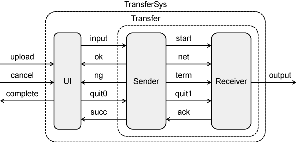 Fig.2. The structure of TransferSys
2. Process Analysis by CONPASU
The symbolic transition graphs generated by CONPASU from TrasnsferSys are
shown in Figures 3 and 4. Graphviz
is used for drawing these graphs.
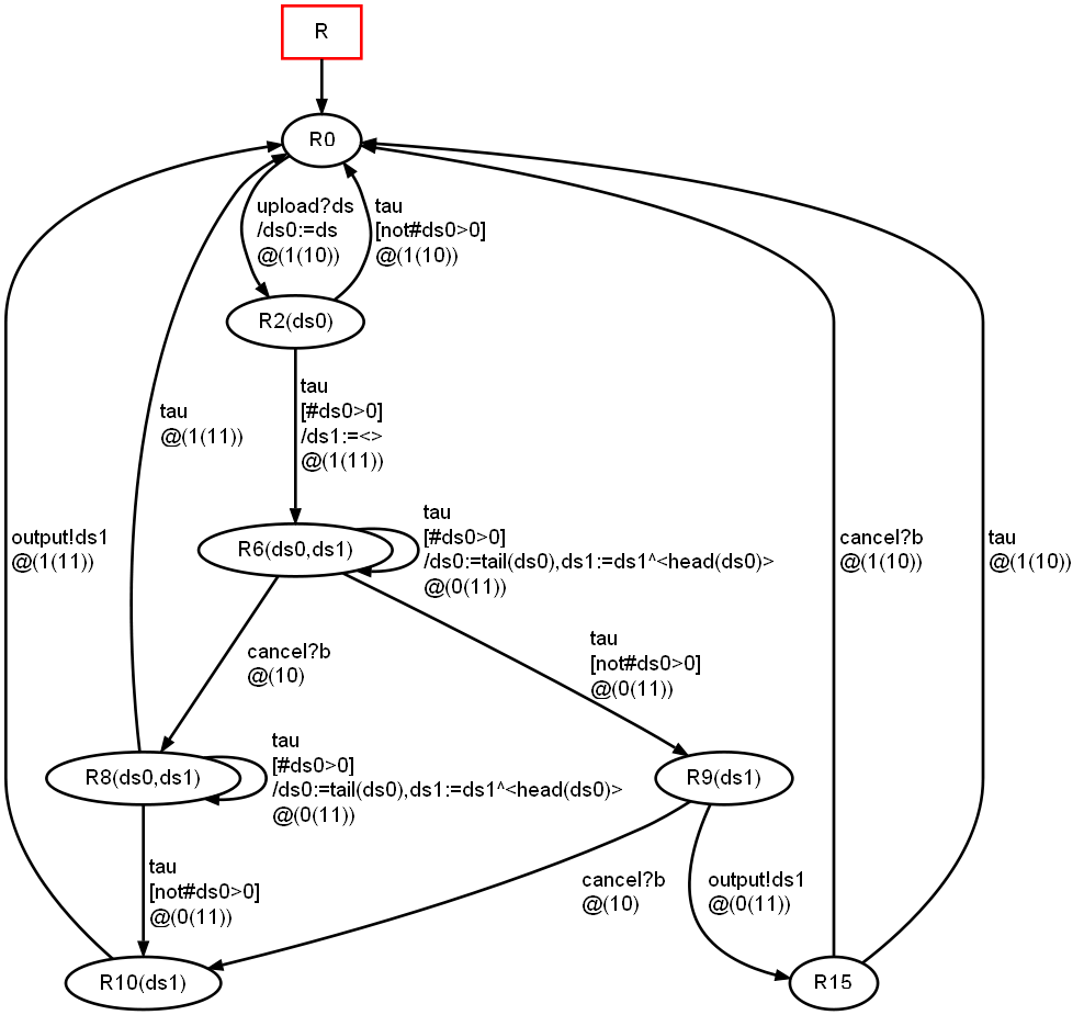
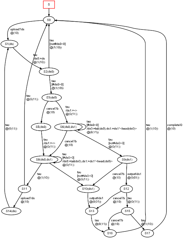 Fig.3. The symbolic
transition graph of TransferSys generated by CONPASU from TransferSys in Fig.1
(Click the graph to magnify it)
Fig.3. The symbolic
transition graph of TransferSys generated by CONPASU from TransferSys in Fig.1
(Click the graph to magnify it)
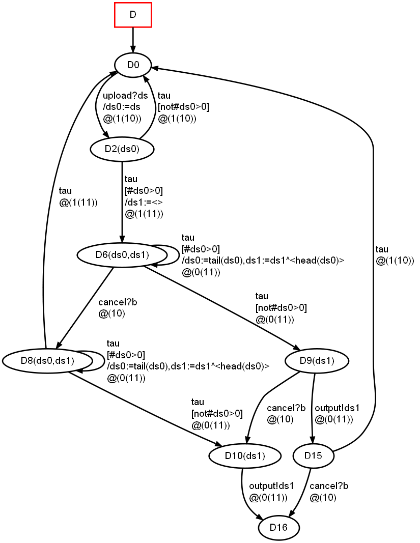
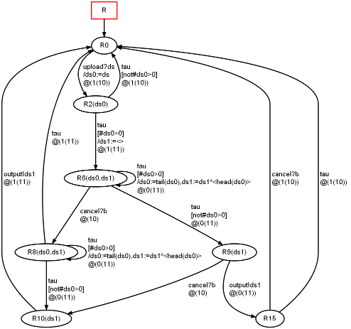 Fig.4. The symbolic transition
graph after hiding "complete" and the state-reduction from Fig.3 (Click the graph
to magnify it)
Fig.4. The symbolic transition
graph after hiding "complete" and the state-reduction from Fig.3 (Click the graph
to magnify it)
The process Term in Figure 1 can receive the quit signal quit0 even
after receiving the acknowledgment. It seems needless, but the system
TransferSys', which is the same as TransferSys except that Term is
replaced by the following Term'
Term' = ack?z -> succ!0 -> Sender,
has a deadlock because it is possible to perform the cancel just after
the successful termination. Figure 5 is the reduced transition graph
generated from TransferSys'\{|complete|}, and it shows how the system
reaches to the deadlock state S16.
 Fig.5. The reduced symbolic
transition graph of TranferSys'\{|complelte|} (Click the
graph to magnify it)
Fig.5. The reduced symbolic
transition graph of TranferSys'\{|complelte|} (Click the
graph to magnify it)