In manual metal spinning, the various senses of the worker, particularly force feeling via the tool, play an important role. Here we investigate the feasibility of force feedback control for robotic metal spinning.
Metal spinning needs much smaller forming force than other plasticity forming techniques, on the order of kilograms instead of tons, because it is based on local and incremental deformation. It involves many control parameters and needs dexterous motion with multiple degrees of freedom. Thus metal spinning can be a suitable task for robot control technology.
Among the various forming parameters in metal spinning, the clearance between the mandrel and roller can be considered the most difficult to set, in view of controlling the forming machinery. The clearance should be exactly controlled equal to the wall thickness after the proces. When the clearance is too large, the precision is degraded because the material does not fully contact the mandrel. This upsets stable forming and wrinkles are likely to occur. Conversely, too small a clearance makes the forming force very large, and the flow of the material sometimes improperly deforms the product.
To obtain an appropriate clearance, the position of the roller relative to the mandrel must be strictly calibrated. The profile of the mandrel should also be exactly known. In addition, the roller should track the desired trajectory precisely under the forming force. When the stiffness of the machinery is insufficient, the set clearance cannot be maintained due to elastic distortion resulting from the forming force.

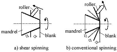
In case of shear spinning with a simple conical mandrel such as Figure a), the wall thickness of the product can be easily predicted. However, it is difficult to know the exact distribution of the thickness if the shape of the mandrel is more complicated, e.g. when the inclination of the surface changes irregularly. In multi-pass conventional spinning in Figure b), in which the material is formed in steps to fit the mandrel, the final thickness distribution is more difficult to estimate. The setting of the clearance fairly depends on the experience of the operators, and it should be adjusted after some forming trials.
Such problems with the clearance setting discussed in the previous section come about because of the position-based control of the forming roller. The desired shape of the product can be obtained by fitting the material tightly to the mandrel. This can be accomplished by pressing the material onto the mandrel with an appropriate force, instead of leaving the clearance between the mandrel and the roller equal to the wall thickness.

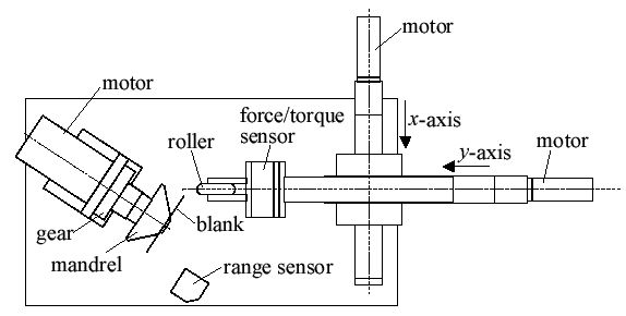
This figure illustrates the experimental setup for metal spinning using force control. The linear motion of x and y axes is driven by the ball-screws and DC servo motors. The mandrel is rotated by a DC servo motor with a planetary gear. The diameter of the forming roller is 70 mm. The roundness of the edge is a 9.5 mm radius. The roller is made from alloy tool steel. A 6-axis force/torque sensor is equipped between the roller and y axis.
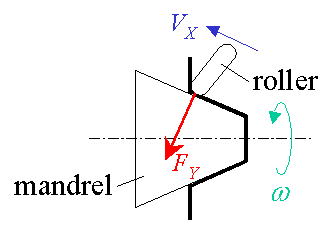
Hybrid position/force control, in which position and force of the roller are simultaneously controlled in each decomposed direction, is applied for shear spinning of a conical product here.

As for the feeding direction X parallel to the mandrel surface, the forming roller is position-controlled in a constant velocity VX. The pushing force FY of the roller normal to the mandrel is controlled to be a constant value FYd.

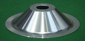
This figure shows an example of the finished product using this control method. The forming is achieved without any failure such as wrinkles.
This method frees metal spinning from the setting of the clearance between the mandrel and roller. Fine positioning of the roller relative to the mandrel is unnecessary. The same value of the pushing force can be used regardless of the stiffness of the machinery. In addition, this method is effective not only for shear spinning but also for final phase of multi-pass conventional spinning when the material is forced onto the mandrel.